Nityanand's Weblog

  • view my stats

    free page hit counter
  • Earn Money by viewing ads

  • Useful Links

How to pass parameters/generic values from the simulator’s command line

Posted by Nityanand Dubey on February 13, 2012


** Note: We have used common term parameters applicable for verilog designs. In VHDL the ‘Generics’ are used for the same.

We use different parameters/generics in the verilog/vhdl designs. Parameters give us huge re-usability of the codes. It means we can use same module/code various times in a big design and each time it’s behavior can be different.

For Example: If I have a parameterized module of a memory instance, where we can configure the length/width of the array by passing the number of words and number of bits through parameters, then we can use same code in various places of a design wherever the memory is needed and the configuration of the instance can be controlled by parameters.

Now, since we have only one module/code which is being used by all the other similar memory instances but different configuration

In the module/code, we provide some default values to the parameter. We need to overwrite the default parameters with the relevant values, If we want to use the module with various configurations,.

Here are the option used by different commonly used industry simulators (VCS, NC-Verilog and ModelSim)

ModelSim: The Parameters value can be passed with ‘vsim’ command in the ModelSim simulator

Assuming we want to supply a parameter value globally to all the modules

-g<param_name>=<param_value>

Example:  All the parameters present in the models named as “simulation_mode” should be active

-g_simulation_mode=yes

Here: “yes” is the value of simulation_mode  to make it as active.

 VCS –

For VCS, Let’s consider another example, say, I want memory ‘A’ with width of 16 bit and Memory ‘B’ width as 64

-pvalue+top/mem_A/No_of_bits=16  -pvalue+top/mem_B/No_of_bits=64

NC-Verilog: To perform same thing the ncverilog uses “defparam” syntax, let’s follow same example as we did in case of VCS –

If you are using 3 step NC-verilog command then following syntax will be used with “ncelab” command line.

Ncelab  […. Other options] -defparam  top.mem_A.No_of_bits=16  -defparam  top.mem_B.No_of_bits=64 

If you are using single step NC-Verilog command then the syntax will look like –

ncverilog [… other options …] +defparam+ top.mem_A.No_of_bits=16

Posted in ASIC Design Flow | Tagged: , , , , , , , , , , , , , | Leave a Comment »

Frequently used CVS Commands

Posted by Nityanand Dubey on November 29, 2010


What is a Version control System?

In simple language, version control system is a database, which stores all the change records of your work. With the help of a version control system, you can make sync in a project while working in a team, whatever change is made by one team member is updated to a common database with the changes/comment/author’s name and the same can be accessed by other peoples whenever is required.

What is CVS?

The CVS (Concurrent Versions System) is a commonly used version control system among the software developers. It gives ease to work on same project by several users. Version control system software keeps track of all work and all changes in a set of files.

Frequently used commands in CVS

Here are some frequently used steps and relevant commands. Before using these commands, make sure the CVS is configured in your working environment and cvsroot is pointing to a desired location.

1. Add a new directory/file in the CVS Database:

cvs add <filename>

This command adds a desired “filename” in the CVS database. Note that this command adds only the file name. To update the file in the database, you need to use the check-in command (described in next point).

This command is used only once with a file/directory at first time.

 2. Checking -in a file into CVS database:

After adding a filename, we need to put the whole file into the database using following commands.

cvs checkin -m “” <filename>

OR

cvs ci -m “” <filename>

 OR

cvs commit -m “” <filename>

Here :

 -m : is a message option to specify any short information about the change You can check in as many as versions of a file and each check in gives you a specific version No of the file

3. Checking out a file from CVS Database

cvs checkout “filename”

OR

cvs co “filename”

Here the filename can be a file or a directory.

The above command brings the latest available version of the given filename. The “filename” may ask to contain relative the path of the cvs directory structure.

4. Checking out a specific version of file.

If you want to get a specific version of file, please use following command –

cvs co -r <version> <file name>

5. Updating the files from database to your environment

This feature works same as CVS checkout. There are some minor changes than the checkout command.

Following command brings the required file(s) which are updated in the CVS but not synced with your environment.

cvs update < filename>

 OR

 cvs up <filename>

 6. Tagging a file:

Tagging is a very useful feature given in the version control system. Suppose, you have achieved an intermediate milestone of a project and you have different files with different versions in the CVS database. Now you want to freeze them for the milestone, then you need to use a tag for them.

You can provide a same tag to all the relevant files from different versions and you can get them anytime by supplying the tag Info.

cvs tag <filename>

You can also use the wildcard characters for any of the cvs application.

7. Checking out a set of file from a given tag.

 Now you want to bring all the files of the given tag.

cvs co -r <filename>

 8. Deleting a tag :

 Following command is used to delete a tag info from a file.

cvs ratg -d <tagname> <filename>

9. Creating a copy of the tag :

 cvs rtag -r <current tag> <new tag> <filename>

10. Retagging of a file .

 Let say after tagging of a set of files, you see an urgent change required in one of the file and you do not want to give any other tag name (due to any reason) for this small change. Then you need to retag the file. Please follow following steps.

A. copy the tag to an another temporary tag (this is required for records that the tag was changed)

cvs rtag -r <current tag> <new tag> <filename>

B. delete the current tag (This is required because you can not give a tag name which is already exists.)

cvs ratg -d  <tag name> <filename>

C.Tag the file with a tagname

cvs tag <tagname> < filename>

11. Finding difference between files from two different versions

 To see the difference in the files form two deferent cvs version can be seen by –

cvs diff -r <version1> -r <version2> <filename>

12. View CVS version information.

The see the log messages, which was given at the time of check in with -m option can be seen by

 cvs log <filename>

To see the status of the file, whether is in sync with the database file of locally modified can be seen using –

cvs status <filename>

To view the tag information with the status use following command

cvs status -v <filename>

Posted in ASIC Design Flow, SHELL | Tagged: , , | 1 Comment »

How to print a file in reversed order in UNIX

Posted by Nityanand Dubey on August 23, 2010


Requirement : Print a file in such a manner that the last line should come at the first like a LIFO

Lets create one example of a file (MyFile) containing following three lines

A
B
C

To print a file in a shell we use the cat command

%cat MyFile
this will print all the contents in a file sequentially.

Output :
A
B
C

%cat –n MyFile
This will print the content with the line numbers

Output :
1 A
2 B
3 C

%cat -n MyFile | sort –nr
This will print the lines into reverse order

Output :

3 C
2 B
1 A

%cat -n MyFile | sort –nr | cut –c 8-

Output :
C
B
A

This will cut the initial 8 characters from each line and prints the desired output.

Posted in SHELL | Tagged: , , , | 1 Comment »

Useful TCL Procedures for array/list handling Part 2

Posted by Nityanand Dubey on April 7, 2010


This post is in a continuation of previous post, which describes the useful procedures for array/list processing in TCL

1. Reducing elements of a given list from other lists.

 proc list1_minus_restlists { list1 args } {
   set list1_less_restlists “”
   set found 0
   set list2 “”
   if { [llength $args] == 0 } {
   puts “*** Error : At least 2 lists are required”;
   return
  }
   for { set i 0 } { $i < [llength $args] } { incr i } {
     for { set j 0 } { $j < [llength [lindex $args $i]] } { incr j } {
      lappend list2 [lindex [lindex $args $i] $j]
     }
   }
      for { set i 0 } { $i < [llength $list1] } { incr i } {
      set found_flag [lsearch -exact $list2 [lindex $list1 $i]]
      if { $found_flag == -1 } {
      set list1_less_restlists [concat $list1_less_restlists [lindex $list1 $i]]
      }
   }
   return $list1_less_restlists
 }

2. To Sort the elementsa in the array.

proc sort_array_of_lists { array1 } {
    set arr_args “”
    upvar $array1 org_array
    if { [array exists org_array] == 0 } {
       puts “*** Error : Please assign an array argument”
    }
    set size [array size org_array]
    set i 0
    foreach { key value } [array get org_array] {
       set sorted_array($i) $value
       set temp_array($key) $value
    incr i
    }
    for { set i 0 } { $i < [expr $size – 1] } { incr i } {
    for { set j [expr $i + 1] } { $j [llength $sorted_array($j)] } {
           set temp $sorted_array($i)
          set sorted_array($i) $sorted_array($j)
       set sorted_array($j) $temp
    }
    }
    }
    for { set i 0 } { $i < $size } { incr i } {
       set index_value [expr [lsearch -exact [array get temp_array] $sorted_array($i)] – 1 ]
       set arg_value [lindex [array get temp_array] $index_value]
       lappend arr_args $arg_value
       set temp_array($arg_value) "ho nahin sakta"
    }
    return $arr_args
   }

3. To find the union of lists in an array

proc union_of_lists_in_array { array1 } {
    set union_lists ""
    global union_of_all_lists
    upvar $arr1 org_array
    if { [array exists org_array] == 0 } {
       puts "*** Error : Please Provide an array"
    }
    set size [array size org_array]
    set i 0
    foreach { key value } [array get org_array] {
       set union_lists [union_of_all_lists $union_lists $value]
    }
    return $union_lists
   }

Posted in TCL | Tagged: , , , , , | Leave a Comment »

Useful TCL Procedures for array/list handling Part 1

Posted by Nityanand Dubey on March 9, 2010


We have to Use different array/list processing during Scripting.

Here are some TCL Procedures for list/array processing.

1. To find the commin elements between two arrays –

proc get_common_in_lists { list1 list2 } {
 set common_list “”
 if { [llength $list1] > [llength $list2] } {
  set list_temp1 $list2
  set list_temp2 $list1
 } else {
  set list_temp1 $list1
  set list_temp2 $list2
 }
 for { set i 0 } { $i < [llength $list_temp1] } { incr i } {
  set found_flag [lsearch -exact $list_temp2 [lindex $list_temp1 $i]]
  if { $found_flag != -1 } {
    set common_list [concat $common_list [lindex $list_temp1 $i]]
  }
 }
 return $common_list
}

2. To find a union of all the lists provided.

proc get_union_of_all_lists { list0 args } {
 set list2 “”
 if { [llength $args] == 0 } {
  puts “*** Error : At least 2 lists are required”;
  return
 }
 for { set i 0 } { $i < [llength $args] } { incr i } {
  for { set j 0 } { $j < [llength [lindex $args $i]] } { incr j } {
   lappend list2 [lindex [lindex $args $i] $j]
  }
 }
 set list2 [concat $list2 $list0]
 set list2 [lsort $list2]
  set union_list [lindex $list2 0]
 for { set i 1 } { $i < [llength $list2] } { incr i } {
  if { [lindex $list2 $i] != [lindex $list2 [expr $i – 1]] } {
   lappend union_list [lindex $list2 $i]
  }
 }
 return $union_list
}

3. To find a list of common elements among given list ( It could be more than two)

proc get_common_in_all_lists { list0 args } {
 set common_list “”
  if { [llength $args] == 0 } {
   puts “*** Error : At least 2 lists are required”;
  return
 }
 for { set i 1 } { $i <= [llength $args] } { incr i } {
  set list($i) [lindex $args [expr $i – 1]]
 }
 for { set i 1 } { $i <= [llength $args] } { incr i } {
  if { [llength $list($i)] < [llength $list0 ] } {
   set temp_list $list($i)
   set list($i) $list0
   set list0 $temp_list
  }
 }
 for { set i 0 } { $i < [llength $list0] } { incr i } {
  set found 1
  for { set j 1 } { $j <= [llength $args] } { incr j } {
   set found_flag [lsearch -exact $list($j) [lindex $list0 $i]]
   if { $found_flag == -1 } {
    set found 0
   }
  }
  if { $found == 1 } {
   set common_list [concat $common_list [lindex $list0 $i]]
  }
 }
 return $common_list
}

Posted in TCL | Tagged: , , , , | Leave a Comment »

Universal Logic : Mux to Logic gates conversion

Posted by Nityanand Dubey on January 7, 2010


We have seen the universal gates in out previous posts. The NAND and NOR are called the universal gates because they can create any of the logic gates.

There is an another concept called “Universal Logic”, Universal logic can also be used to create any of the logic gates.

MUX and Decoders are called “Universal Logic”

In this post, we will see haw a 2:1 MUX can be used to create different logic gates.

1. Designing an Inverter using 2:1 MUX.

To design an inverter using 2:1 mux, we have to use the input as the select line of the MUX and the “zeroth” select line would be tied with “Logic 1 ” and “First” select line would be tired with “Logic 0”, Now when the select line (Input) goes to “1” the out put will be “0” ( inverted).

Image : MUX to inverter –

2:1 mux as an inverter

2. Designing an AND Gate using 2:1 MUX.

To design an AND using 2:1 mux, we need to tie the “zeroth” input to “Logic 0” and the “First” input to the one of the input of the AND Gate. The other input of AND gate would be connected with the select line of the MUX.

Now, the out put of the MUX would be “1” only if the both of the inputs are “1” otherwise it would be “0” for all conditions.

Image : MUX to AND Gate –

2:1 MUX as an AND gate

3. Designing an OR Gate using 2:1 MUX.

To design an OR using 2:1 mux, we need to tie the “First” input to “Logic 1” and the “Zeroth” input to the one of the input of the OR Gate. The other input of OR gate would be connected with the select line of the MUX.

Now, the output of the MUX would be “1” when any oth the two inputs would be “1” otherwise it would be “0” for all conditions.

Image : MUX to OR Gate –

2:1 MUX as an OR Gate

4. Designing an NOR Gate using 2:1 MUX.

To design the NOR using 2:1 mux, we need to tie the “Zeroth” input of mux to one of the input of NOR and another input of MUX is tied to “0” . The another input of NOR gate would be applied to the select line of the MUX.

Now, the output of the MUX would be A’B’ = (A+B)’. which is as same as the output of NOR Gate.

Image : MUX to NOR Gate –

2:1 mux as a NOR Gate

5. Designing an NAND Gate using 2:1 MUX.

To design the NAND using 2:1 mux, we need to combine the AND Gate and inverter implementation

6. Designing an XOR Gate using 2:1 MUX.

To design the XOR using 2:1 mux, we need to tie the “Zeroth” input of mux to one of the input of XOR and another input of MUX to the inverted of first input. The another input of XOR gate would be applied to the select line of the MUX.

Now, the output of the MUX would be AB’ + A’B which is as same as the output of XOR Gate.

Image : MUX to XOR Gate –

2:1 Mux as a XOR gate

7. Designing an XNOR Gate using 2:1 MUX.

To design the XNOR using 2:1 mux, we need to tie the “First” input of mux to one of the input of XOR and another input of MUX to the inverted of first input. The another input of XOR gate would be applied to the select line of the MUX.

Now, the output of the MUX would be A’B’ + AB which is as same as the output of XNOR Gate.

Image : MUX to XNOR Gate –

2:1 mux as a XNOR Gate

Posted in Digital Design | Tagged: , , , , , , , , , | 29 Comments »

What is a Universal Gate and Why NOR is called a Universal gate?

Posted by Nityanand Dubey on December 4, 2009

This is a continuation of previous post, in this post, we will see the NOR gate as a univarsal gate and create different gates using NOR gate.

As we know that NAND and NOR Gates are called Universal Gates since they can cerate any of the Logic Gate

Lets see to how to make all other logic gates by using the NOR Gate

1. NOR gate to NOT Gate conversion

Refer the following diagram –

Digital : Image – NOR to NOT

NOR to NOT Conversion

NOR to NOT Conversion

Here the same input is applied to the both inputs of a NOR Gate

According to NOR Gate – If A and B are two inputs than output equation will be (A+B)’

For this case :

= (X+X)’
= X’
= Inverted Input

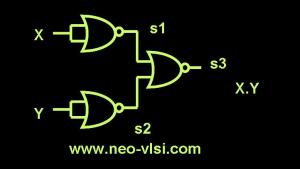
2. NOR Gate to AND Gate Convertion

Refer following diagram for NOR to AND Gate conversion –

Digital : Image – NOR to AND Conversion

NOR to AND Conversion

NOR to AND Conversion

According to diagram –

s1 = (X+X)’ = X’
s2 = (Y+Y)’ = Y’
s3= (s1+s2)’ = (X’+Y’)’
=> (X’)’ .(Y’)’
=> X.Y
=> AND Gate

3. NOR Gate to OR Gate Convertion

Refer the following Diagram

Digital : Image – NOR to OR Convertion

NOR to OR

NOR to OR


For this case – X and Y are the two inputs to a NOR gate and the output of the First NOR gate goes again to an another NOR gate’s inputs.

=> s1 = (X+Y)’
=> s2 = (s1+s1)’ = s1’
=> s2 = ((X+Y)’)’
=> X+Y

=> OR Gate

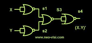
4. NOR Gate to NAND Gate Convertion

Refer the following Diagram

Digital : Image – NOR to NAND

NOR to NAND Conversion

NOR to NAND Conversion


According to diagram –

s1 = (X+X)’ = X’
s2 = (Y+Y)’ = Y’
s3 = (s1+s2)’ = (X’+Y’)’
=> (X’)’ .(Y’)’
=> X.Y
s4 = (s3 + s3)’
=> s3′
=> (X.Y)’
=> NAND Gate

5. NOR to XOR Gate

Digital : Image – NOR to XOR Gate Convertion

6. NOR to XNOR Gate

Digital : Image – NOR to XNOR Gate Convertion

Posted in Digital Design | Tagged: , , , , , , | 2 Comments »

Using event based modeling in verilog to avoid Racing between always blocks.

Posted by Nityanand Dubey on November 28, 2009


In most of our designs, we have to perform some operation on the posedge of clock. To implement this, we normally use different always block with the posedge of clock in the sensitivity list.

Some times, we need to use the signal in one always block, which is getting assigned a value from another, and here the actual problem starts.

Since the all the always blocks execute concurrently in the design, which may create racing between signals, which is again varies among simulator to simulator.

For this scenario, the signals may get value from one always block before/after it is used in another one.

Using “event” in the verilog programming can be one way to take care this kind of situation.

Example 1 :

Here two always blocks are shown,

In this case we are trying to set some modes by looking into some conditions. Also, we want to use the modes at the posedge of clock and perform some other operation.

Since both always blockes are working at the same posedge of clock, which may create a racing between the mode signals.

This is a small example but in real-time scenario, it might be more complex and big.

It may take the new value of mode of continue with the older value, depends on the simulator’s algorithm.

Block – 1 :

always (posedge clock)
begin
    if (condition1)
        mode1 = 1’b1;
    else if (condition2)
        mode2 = 1’b1;
    else
        mode3 = 1’b0;
end

Block – 2 :

always (posedge clock)
begin
    if( mode1 && conditions3)
        output <= input1;
    else if (mode2 && condition4)
        output <= input2
    else
        output <= 2’b0;
end

Now, Lets try to avoid the racing between these two always blocks.

Here, we use an “event” to trigger the other always block, and the triggering will take place at the last of first always block.

Since we wanted to run the both always block at the posedge of the clock, which is also happening here.

By using the event in the sensitivity list of other always block makes sure that this block will execute when the first will be completed, and it will be able to use the new values assigned to the mode variables.

We can have multiple events in the design.

// event declaration
event ev_mode

Block – 1 :

always (posedge clock)
begin
    if (condition1)
        mode1 = 1’b1;
    else if (condition2)
        mode2 = 1’b1;
    else
        mode3 = 1’b0;
    -> ev_mode
end

Block – 2 :

always (ev_mode)
begin
    if( mode1 && conditions3)
        output <= input1;
    else if (mode2 && condition4)
        output <= input2
    else
        output <= 2’b0;
end

Posted in VERILOG | Tagged: , , , , , , | 1 Comment »

Design synthesis and relevant verilog code for DFF

Posted by Nityanand Dubey on March 31, 2009

For RTL Coding, one should know that what code will infer which hardware in the design and vise versa.

The Design engineer should be aware of relevant code and the output logic so he can be able to minimize the design and the no of gates using.

In this post we will see deferent DFF and their verilog codes

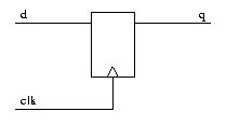
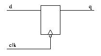
DFF ( D- Flip-Flop)

reg q;

always @ (posedge clk)
q <= d;

In this code, the value of D(data) will be assigned to output (q) at the posegde of the clock and it will remain untouched till next posedge of the clock since the q is defined as reg.

D-Flip Flop

D-Flip Flop

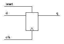
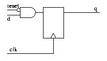
DFF ( D- Flip-Flop) with Asynchronous reset.

reg q;

always @ (posedge clk or posedge reset)
if (reset)
q <= 1’b0;
else
q <= d;

According to above code, the reset is positive edge triggered and asynchronous so it is kept in the sensitivity list of always block with the posedge.

Inside the always block, there are a conditional statement to check whether the reset is true (1), otherwise it behaves as normal DFF

DFF - Async Reset

DFF - Async Reset

DFF ( D- Flip-Flop) with synchronous reset

reg q;

always @ (posedge clk)
if (reset)
q <= 1’b0;
else
q <= d;

Synchronous reset means the flop will be reset only with the posedge of clock, hence the sensitivity list does not have the reset signal; However it check the reset for true whenever the posedg of clock comes.

DFF - Sync Reset

DFF - Sync Reset

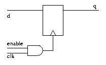
DFF ( D- Flip-Flop) with gated clock.

reg q;
wire gtd_clk = enable && clk;

always @ (posedge gtd_clk)
q <= d;

Many times it becomes required to apply clock to the design only when the enable is active. This is done by the gated clock. The clock and enable both are the inputs to a and gate and the output of the gate goes to the clock input of the flop.

DFF - Gated Clock

DFF - Gated Clock

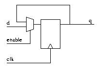
Data Enabled DFF

reg q;

always @ (posedge clk)
if (enable)
q <= d;

Data Enabled flops has a mux at the data input, which is controlled by the enable signal. Now even the posedge of clock comes to the flop, flop will not change the value until enable is not active.

DFF - Data Enable

DFF - Data Enable

Negative Edge triggered DFF

reg q;

always @ (negedge clk)
q <= d;

In this code, the value of D(data) will be assigned to output (q) at the negedge of the clock and it will remain untouched till next negedge of the clock since the q is defined as reg.

DFF -Negative Edge

DFF -Negative Edge


Posted in ASIC Design Flow, VERILOG | Tagged: , , , , , , | Leave a Comment »

What is Timescale in verilog codes

Posted by Nityanand Dubey on March 18, 2009

The ‘timescale is one of the compiler directive to specify the unit for the delays used in the design with their precision.

The timescale line is very important in the verilog simulation, because there are no any default delays specified by the verilog.

Syntax :

`timescale <time unit>/<time precision>

Here :

time unit : This is the time to be used as one unit for all the delays used in the design.

time precision : This represents the minimum delay which needs to be considered during simulation or it decides that how many decimal point would be used with the time unit.

Range of Timescale :

The range for time unit can be from seconds to femto-seconds, which includes all the time units including s (second), ms(mili-second), us(micro-second), ns(nano-second), ps(pico-second) and fs(femto-second).

Example :

`timescale 1ns/1ps

Here :

1ps = 0.001 ns

#1; // = 1ns delay

#1.003; // = will be considered as a valid delay

#1.0009; // = will be taken as 1 ns only since it is out of the precision value.

Posted in VERILOG | Tagged: , , , | 3 Comments »